wokwi-ky-040 Rotary Encoder Reference
KY-040 Rotary Encoder module with 20 steps per revolution.
Pin names
| Name | Description |
|---|---|
| CLK | Rotary encoder pin A |
| DT | Rotary encoder pin B |
| SW | Push button pin. Normally open, shorted to GND on press |
| VCC | Voltage supply |
| GND | Ground |
Operation
The rotary encoder offers two ways of interaction:
- Rotation - You can rotate the knob by clicking on the arrows. The upper arrow rotates it one step clockwise, and the lower arrow rotates it one step counterclockwise. Rotating the knob will produce digital signals on the DT and CLK pins, as explained below.
- Button - Click on the knob to press the button. While pressed, the button connects the SW pin with the GND pin.
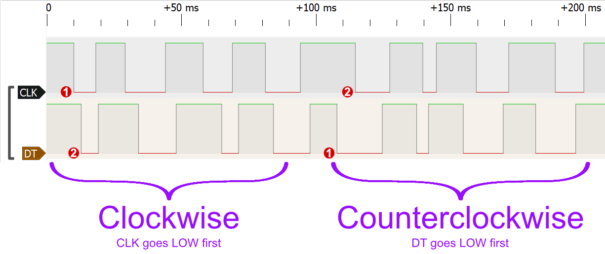
Every time the user rotates the knob, it produces a LOW signal on the DT and CLK pins:
- Rotating clockwise causes the CLK pin to go low first, and then the DT pin goes low too.
- Rotating counterclockwise causes the DT pin to go low first, and then the CLK pin go low.
Both pins will go back high within a few milliseconds. The following diagram illustrates this:
You can experiment with the DT/CLK pin timings by connecting them to the Wokwi Logic Analyzer. Check out the Logic Analyzer Guide to learn how to use the logic analyzer.
Schematics
The KY-040 module includes two internal pull-up resistors that pull-up pins CLK and DT to VCC. The simulation always pulls these pins up, even if you left the VCC pin floating.

Using the Rotary Encoder in Arduino
Reading the rotation
You can read the rotation by checking the status of the CLK pin. Whenever it goes LOW, read the value of the DT pin to determine the direction: HIGH means clockwise rotation, LOW means counterclockwise rotation. Code example:
#define ENCODER_CLK 2
#define ENCODER_DT  3

void setup() {
  Serial.begin(115200);
  pinMode(ENCODER_CLK, INPUT);
  pinMode(ENCODER_DT, INPUT);
}

int lastClk = HIGH;

void loop() {
  int newClk = digitalRead(ENCODER_CLK);
  if (newClk != lastClk) {
    // There was a change on the CLK pin
    lastClk = newClk;
    int dtValue = digitalRead(ENCODER_DT);
    if (newClk == LOW && dtValue == HIGH) {
      Serial.println("Rotated clockwise ⏩");
    }
    if (newClk == LOW && dtValue == LOW) {
      Serial.println("Rotated counterclockwise ⏪");
    }
  }
}
You can also run this example on Wokwi.
Note: your code will need to read the state of the pins frequently in order to detect the rotations
correctly.
If your loop() takes too long (e.g. you use delay() in your code), we recommend using attachInterrupt() to listen for changes in the CLK pin. Assuming CLK is connected to pin 2, and DT to pin 3 (as before):
#define ENCODER_CLK 2
#define ENCODER_DT  3

void setup() {
  pinMode(ENCODER_CLK, INPUT);
  pinMode(ENCODER_DT, INPUT);
  attachInterrupt(digitalPinToInterrupt(ENCODER_CLK), readEncoder, FALLING);
}

void readEncoder() {
  int dtValue = digitalRead(ENCODER_DT);
  if (dtValue == HIGH) {
    Serial.println("Rotated clockwise ⏩");
  }
  if (dtValue == LOW) {
    Serial.println("Rotated counterclockwise ⏪");
  }
}

void loop() {
  // Do whatever
}
Using the button
To read the state of the encoder's button, connect to to any Arduino IO pin and initialize this pin as INPUT_PULLUP. Then read the state of the button using digitalRead().
It'll read LOW as long the the button is pressed.
The following code example will turn on Arduino's built-in LED (13) as long as the button is pressed. It assumes you connected the SW to Arduino pin 4. You also need to connect the GND pin to one of the Arduino's GND pins.
#define ENCODER_BTN 4

void setup() {
  pinMode(ENCODER_BTN, INPUT_PULLUP);
  pinMode(LED_BUILTIN, OUTPUT);
}

void loop() {
  if (digitalRead(ENCODER_BTN) == LOW) {
    digitalWrite(LED_BUILTIN, HIGH);
  } else {
    digitalWrite(LED_BUILTIN, LOW);
  }
}
Keyboard control
To control the rotary encoder with the keyboard, first click on it, then use the following keys:
| Key | Function |
|---|---|
| Right / Up | Rotate one step clockwise* |
| Left / Down | Rotate one step counterclockwise* |
| Spacebar | Press the button |
* Hold down the arrow keys to continuously rotate the encoder, generating a series of pulses on the CLK/DT pins.