Getting Started with the Wokwi Custom Chips C API
The Chips API is currently in beta. Please share your experiments and provide feedback in the #custom-chips channel on the Discord chat.
Introduction
The Custom Chips API allows you to create new simulation models and extend the functionality of Wokwi. You can create new sensors, displays, memories, testing instruments, and even simulate your own custom hardware.
Custom Chips are usually written in C, but you can use any language that compiles to WebAssembly (e.g. Rust, AssemblyScript, etc.). There is also an experimental support for writing custom chips in Verilog.
Tutorials
- Video Tutorial - Three chip examples in 15 Minutes
- Step-by-step blog tutorial - Create a 7-segment driver chip from scratch
- I2C chip tutorial - Coding a PCF8575 I/O expander from scratch
Getting started
Open any Wokwi project (or create a new one) and click on the blue "+" button in the diagram editor. Select "Custom Chip" from the list of options.
You'll see a dialog where you can enter the chip name, as well as the language you wish to use. We recommend using C for now. After typing a name for your chip, click on the "Create Chip" button.
This will add a copy of the chip to your diagram and create two files in your project:
- a JSON file with the chip pinout and settings (name, author, etc.)
- a C file with the chip code (or a rust/verilog file, depending on the language you selected).
The JSON file file defines a minimal set of pins ("VCC", "GND", "IN", "OUT"). Change the pin names and add more pins as needed.
The C file contains a minimal chip implementation. Add your code to the chip_init() function. This function is called for every instance of the chip in the diagram. You can use it to initialize the chip state, configure timers, and set up pin watches.
The example code also includes a chip_state_t struct, where you can store any state that your chip needs. You can use the user_data field of the i2c_config_t, timer_config_t, etc. to store a pointer to this struct.
Debugging your custom chip
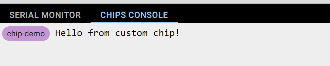
You can print debugging messages using the standard C printf() function. Make sure to also #include <stdio.h> in your program. The debug messages will appear in a new "Chips Console" tab below the diagram view:
In addition, you can use the Wokwi Logic Analyzer to debug the communication with your custom chip.
Make sure to include a newline ("\n") at the end of your printf() messages. The simulator shows the messages only when it reaches a newline character.
Chips API reference 📖
- GPIO pins API
- Analog API
- Time simulation API
- UART API
- I2C Device API
- SPI Device API
- Attributes
- Framebuffer API
Chip examples
Basics
- Digital Inverter - Inverts the input signal
- XOR gate - Implements a XOR gate
- Timer Chip - Showing how to use the Time API and create timers
Communication
- SPI Chip - A basic ROT13 cipher over SPI
- UART Chip - A basic ROT13 cipher over UART
- I2C Chip - Simple counter with interrupt output
- EEPROM Chip - Simple I2C memory with 256 kbits by Benny Meisels
Displays
- Framebuffer Chip - Shows how to implement a custom display driver chip
- SSD1306 Display - 128x64 monochrome OLED display chip (using I2C)
- SH1107 Display - 128x128 monochrome OLED display chip (using I2C)
- IL9163 Display - 128x128 color LCD display chip (using SPI)
Sensors
- LM75A Chip - I2C digital temperature sensor
- I2C Keypad Driver Example by Yewolf
- DS18B20 Chip - Dallas Semi DS18B20 Temperature Sensor over OneWire by Bonny Rais
Complex chips
- CD4051B Multiplexer Example - Analog Multiplexer by Chris Schmidt
- PCA9685 Chip - 16-channel PWM driver over I2C by Bonny Rais
- Live 8-channel Logic Analyzer with Protocol Decoding - Live logic analyzer with UART, I²C and SPI decoding by Gil Tal (GitHub)